The Omron E5CC temperature PID controller is using modbus RTU(Remote Terminal Unit) to connect.
First, you prepare a USB-to-RS-485 cable. Connect it to the E5CC. Notice that the A port of the E5CC, should be connected to negative of the RS-485. Don’t follow the E5CC manual. Also the programing manual is extremely for expert of modbus, not for beginner.
In Modbus, the idea is that, your PC (master) send signal over the connected devices (slaves). The signal is a Hex, contained few things
DeviceID + Function-Code + Address + Command-in-Hex + CRC-16
The master send a signal, only the device with matching DeviceID will respond to the signal. Thus, there is no “locking” that link the master-slave.
The Function-Code is modbus function code, it tell the type of the signal. The type can be reading, writing, diagnostic, etc. This function is part of the modbus protocol, which is common for all devices.
The Address is the memory address stored in the device. The address should be provided by the device manufacture.
Then the command-in-Hex follow.
At the end, a 4-digit Hec CRC-16 is used for error check. Qt can calculate CRC-16 for modbus.
Read single value
In the Omron E5CC programing manual. Section 4-4-1, we see that the data structure of a read signal. It is read because the Function-Code is 0x03, which is “Read Holding Registers” in modbus RTU protocal. For example, reading the temperature (PV) of E5CC,
01 03 00 00 00 02 C4 0B
0x01 is deviceID, this can be set in the E5CC.
0x03 is the function code
0x0000 is the address
0x0002 is number of value we are going to read. In modbus, one value contains 4-digit Hex, or 0xHHHH. In E5CC, each parameter is stored as 8-digit Hex, or 0xHHHHHHHH. Thus the E5CC manual tell us to get 2 values for temperature reading.
0xC408 is the CRC-16
The device return
01 03 04 00 00 03 E8 FA 8D
04 is the number of 8-digit Bin (2-digit Hex = 8-digit Bin). Four of 8-digit Bin = 8-digit Hex.
00 00 03 E8 is the return value of the temperature, converted to DEC is 1000, which is 100.0 ºC.
Write single value
Run/Stop command
01 06 00 00 01 01 49 9A
0x06 is the “Write Single Register” function-Code
0x0000 is the address
0x0101 is the value that start the run/stop for E5CC.
When writing single value in E5CC, only address 0x0000 is allowed. Thus, to write the SV (set value, or SP = Set Point) we have to use write multiple value. (stupid….)
Write multiple value
The set the alarm upper and lower values
01 10 01 0A 00 04 08 00 00 03 E8 FF FF FC 18 8D E9
0x10 is the “Write Multiple Coils”
0x010A is the address of the alarm upper value
0x0004 is the 2 times number of value to be written. In our case, we want to write 2 value, thus the value is 0x4. The address of the next value would be 0x010A + 0x0002 = 0x010C. Since all value use 2 memory slots.
0x08 is the length of the input value. There are 2 value, each value is four 4-digit-Hex, so the input is 0x08.
0x000003E8 is the first value
0xFFFFFC18 is the 2nd value
This structure can also be use to write single value. If we want to change the SV (or Set Point) to 100 ºC. The address is 0x0106.
01 10 01 06 00 02 04 00 00 00 64
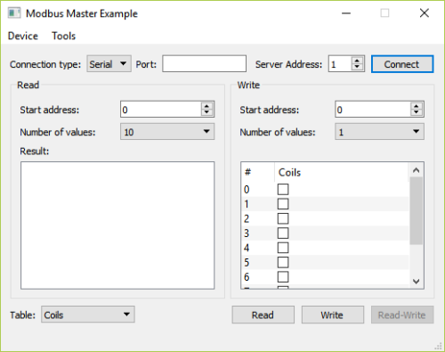
In Qt, there is an example for modus, call master. We can use it for simple I/O.
Here is a screenshot.
First, we go to Tools to setup the Setting
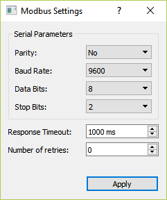
In the E5CC, you have to set the communication mod to be modbus. In modbus, the parity, data bits, and stop bits are no used.
Since we use USB, this is serial port. The port number can be found using
const auto infos = QSerialPortInfo::availablePorts();
for (const QSerialPortInfo &info : infos) {
        qDebug("PortName     ="+info.portName())
        qDebug() <<"description  =" << (!info.description().isEmpty() ?  info.description() : blankString);
        qDebug() <<"manufacturer =" << (!info.manufacturer().isEmpty() ? info.manufacturer() : blankString);
        qDebug() <<"serialNumber =" << (!info.serialNumber().isEmpty() ? info.serialNumber() : blankString);
        qDebug() <<"Location     =" << info.systemLocation();
        qDebug() <<"Vendor       =" << (info.vendorIdentifier() ? QString::number(info.vendorIdentifier(), 16) : blankString);
        qDebug() <<"Identifier   =  << (info.productIdentifier() ? QString::number(info.productIdentifier(), 16) : blankString);
}
In my case, it is COM4, so I put COM4 in the port. Then connect.
The read the temperature. We set the Table (at the lower left corner) to be Holding Register. In the Read (left panel), Start Address is 0, and Number of values to be 2. In the Qt application output, we will see:
qt.modbus: (RTU client) Sent Serial PDU: 0x0300000002
qt.modbus.lowlevel: (RTU client) Sent Serial ADU: 0x010300000002c40b
qt.modbus: (RTU client) Send successful: 0x0300000002
qt.modbus.lowlevel: (RTU client) Response buffer: “010304”
qt.modbus: (RTU client) Incomplete ADU received, ignoring
qt.modbus.lowlevel: (RTU client) Response buffer: “0103040000001cfbfa”
qt.modbus: (RTU client) Received ADU: “0103040000001cfbfa”
The PDU = Protocol Data Unit, ADU = Accessing Data Unit = DeviceID + PDU + CRC-16. In the last line, the received PDU is 0x03040000001c, the value is 0x0000 and 0x001c=28, which is 18 ºC.
The display in the GUI is:

Now, we try to stop the device.
In the write panel, Start address is 0x0000, and according to the E5CC programing manual, the value consist of two part
AA BB
AA is the command code
BB is the value
From the manual, the command code for RUN/STOP, 0xAA=0x01, and for STOP 0xBB=0x01. Thus, the value is 0x0101. Then we press write.

The Qt application output is
qt.modbus: (RTU client) Sent Serial PDU: 0x0600000101
qt.modbus.lowlevel: (RTU client) Sent Serial ADU: 0x010600000101499a
qt.modbus: (RTU client) Send successful: 0x0600000101
qt.modbus.lowlevel: (RTU client) Response buffer: “01”
qt.modbus: (RTU client) Modbus ADU not complete
qt.modbus.lowlevel: (RTU client) Response buffer: “010600000101499a”
qt.modbus: (RTU client) Received ADU: “010600000101499a”
And we can see there is a STOP display on the E5CC.
We can see, although the Holding Register is the same, in read, the function code is 0x03, in write, the function code is 0x06. In Qt manual, the QModBusPdu Class, we can see a list of Function-Code. (https://doc.qt.io/qt-5/qmodbuspdu.html#FunctionCode-enum)
This program is limited 10 address, so the operation is limited. This introduction is the basic, I think user can can study the Qt code to know how to use modbus, how to read and write signal. And people can read this website for another modbus 101.


 are integer.
 points are known with finite
  .
.
 , and then the time axis becomes an integer number axis. We found that
  as the wavelet can only be expand, not shrink. Because there are finite number of data point, i.e.
  ,
,  .
. is very time consuming. There is a

 are integer. The set of shifted scaling function span a space
  . For the wavelet,

 , so that
  , so that
 and
and  are related. In fact, the relationship for orthonormal scaling function and wavelet is
 , it can be decomposed into the MRA space. We start by the largest
 and
and  space. We can use the nested property of the MRA space,
  can be decomposed into
  and
and  ,
,
 and
and  are orthonormal ),

 and
and  , the wavelet coefficient
  can be decomposed to


 are related to
  . For orthonormal wavelet,

 are all finite. That greatly reduce the computation cost of the discrete wavelet transform.
 , we don’t need to use
 ,
,


